


CDS is renowned as one of the foremost specialist distributors and suppliers of LCD TFTs and value added services for these products, many of which can be found at the 2 links below. But we wanted just to highlight some of the interfacing points for LCDs including the controllers, timings, picture elements etc. as such information is not always easy to find. We hope you find it interesting or if you know this already it acts as a refresher to your already in-depth LCD knowledge and the driving of these displays.
https://crystal-display.com/products/cds-small-format-tft-range/
https://crystal-display.com/category-components-displays-manufacturers/
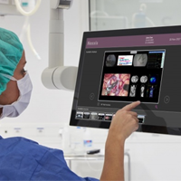
CDS’s wide range of TFT LCDs will deliver a vibrant, high contrast user interface to any application. Our TFT displays are available in a wide range of sizes, designs, and formats and are easy to incorporate into any design. CDS offers the most popular and cost-effective Amorphous Silicon Thin Film Transistor or a-SiTFT panels. This BLOG POST is an application note that discusses how to drive a TFT LCD using widely available microprocessors.
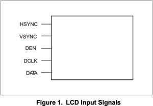
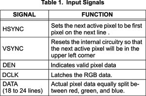
CDS TFT vary depending on the input mode and interface etc. but a number typically have the input signals shown below in Figure 1 and described in Table 1 (although by no far exclusively, and these are just examples for engineers).
Some small, lower end panels may not have all of the electronics included with them because of size or cost restraints. Some panels have a simple row and column driver interfaces. Some may need an external timing controller. Some have a processor bus type Interface.
Depending on internal circuitry demands, some panels may include a few other signals, such as a reset line. Determining how to drive such simple signals is usually straightforward.
Many LCD controllers, including those integrated into microcontrollers, will directly drive the signals shown in Figure 1. This means that the biggest obstacle to quickly getting an image on the screen is generating the appropriate signal timing. The LCD controller is responsible for generating the timing; however software must be written to correctly program the controller for the specific LCD model.
MECHANICAL CONSTRAINTS OF AN LCD PANEL
An LCD panel comprises a matrix of pixels (picture elements), divided into red, green, and blue “sub-pixels”. Each sub-pixel is driven by a small transistor. Typically, LCD panels have internal row and column drivers, much like DRAM. A row is selected by the row driver, then the column driver sequences through each of the columns. After each of the columns has been written, the row driver selects the next row and the process repeats. The VSYNC signal resets both row and column drivers to the upper left pixel. The HSYNC causes the row driver to step to the new row. The clock sequences the column driver through each of the pixels, with each clock edge latching data values for the red, green, and blue sub-pixels. These values drive a form of D/A converter to store an electrical charge in a capacitor in each sub-pixel which controls the drive of the transistor; this in turn controls the brightness of the sub-pixel. A red-green-blue colour mask is used to filter the light from each sub-pixel to form its corresponding colour.
Like a DRAM, an LCD panel must be constantly refreshed or the image will fade. Most TFT LCD panels work when refreshed around 60 Hz. The image data is usually held in a section of main memory called a frame Buffer.
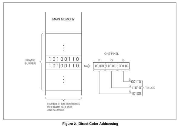
Each location in the frame buffer corresponds to a pixel on the LCD. The value in the location determines the colour displayed for that pixel. See Figure 2. The size of the frame buffer depends on two things; 1. the number of locations needed, and 2. the size of each location.
The total number of locations needed is determined by the panel resolution. For instance, let’s take the resolution of a panel is 320 × 240 pixels. 320 × 240 = 76,800 memory locations will be needed in the frame buffer „ one for each pixel.
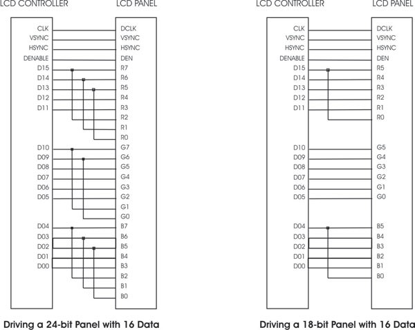
TFT panels typically have an input of at least 6 bits of red data, 6 bits of green data, and 6 bits of blue data. A panel with 6 red, 6 green, and 6 blue data lines is termed a 6-bit panel. If the processor or LCD controller doesn’t drive as many data lines as the panel requires, use the data line configuration shown in Figure 3 or Figure 5.
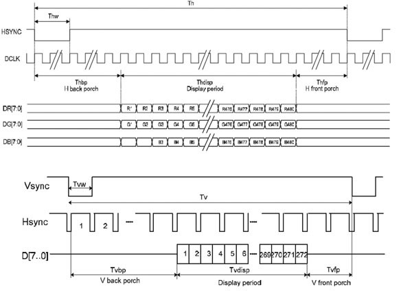
TOTAL CLOCKS(TH) = HSYNC WIDTH(THp) + BACK PORCH(THe) + VALID DATA (THd) + FRONT PORCH
The Valid Data time (THd) is equal to the number of pixels in the horizontal direction, in this case 320. From the Timing Table we see that the typical value for the HSYNC pulse (THp) is 12, and the typical number of total clocks per line is 400.
The remaining 400 … 320 … 12 = 68 clocks can be split in any combination between the back porch and the front porch as long as all minimums and maximums are met.
The vertical timing is split into the same four areas as the horizontal timing. The formula is: TOTAL LINES(TV) = VSYNC WIDTH(TVp) + BACK PORCH(TVs) + VALID DATA(TVd) + FRONT PORCH
We hope the above information has been of use and please check out our wide range of LCDs, TFTs, and OLED Products as we are sure we will have a display that would be ideal for your application.
You can find more information clicking the link here https://crystal-display.com/products/cds-small-format-tft-range/
For more information please email info@crystal-display.com or call our main office on +44 (0) 1634 327 420.